
Sony PS2 Guncon 2 Trigger Kit Guide
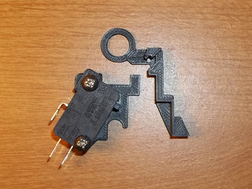
1. Introduction
This kit installs a microswitch inside of the Playstation 2 Guncon 2, for improved tactility and more accurate trigger pulls. It also works as a fix for triggers with broken switch actuators (which is a common issue, because the original plastic is so thin).
Note that there could be some dimensional variance in the injection molded parts that the 3D printed parts fit into. You may have to perform some filing or use a razor/sharp knife to widen holes if things are too tight. I design these kits to be snug as it's better to have excess material instead of 'not enough.'
This kit was primarily designed for the 'Made in Japan' NPC-106 model which has black screws. If you have the 'Made in China' version with silver screws, the kit will work, but please review additional instructions at the end of the guide to fit the trigger piece, as it is slightly different.

2. Opening & Prep
Be aware that this mod is a little more complicated than other light gun switch kits since the interior of the Guncon 2 is very crowded. Unscrew the six screws holding the shell together and set the upper half aside.

3. Inspection
Take a note of the general layout and unplug the cord from the PCB above the B button, or simply move it aside. You'll also want to move the magazine bottom button out of the way.
4. Fitment
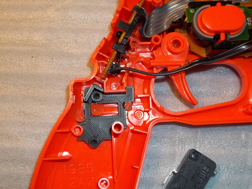
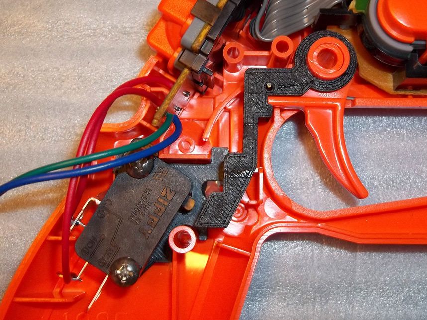
Place the switch bracket as pictured, it's designed to be a snug fit, but there appears to be enough variation in ABS injection molding that you should secure it with a couple dots of hot glue so that it never shifts out of alignment.

5. Solder Points
Remove the trigger/d-pad PCB and desolder or clip out the original trigger button, then solder wires to the points shown.

6. Wiring Switch
Connect the wires to the common and normally-open tabs of the switch and screw the switch into place if you haven't already. Note that you may have to bend the normally-open tab as shown so that it clears the interior plastic of the Guncon shell. You may also want to extend the wires of the magazine button below as it will make things much easier for reassembly when the time comes.
7. Trigger Prep
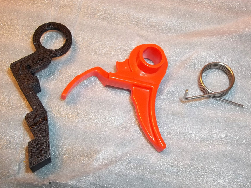
The second half of the switch kit mates with the original trigger to extend its reach- be very careful applying this, you might have to file, sand or shave a little inside the hole that slips over the circular peg of the trigger. Designed to be a snug fit, but excessive force shouldn't be necessary.
8. Trigger Fitment
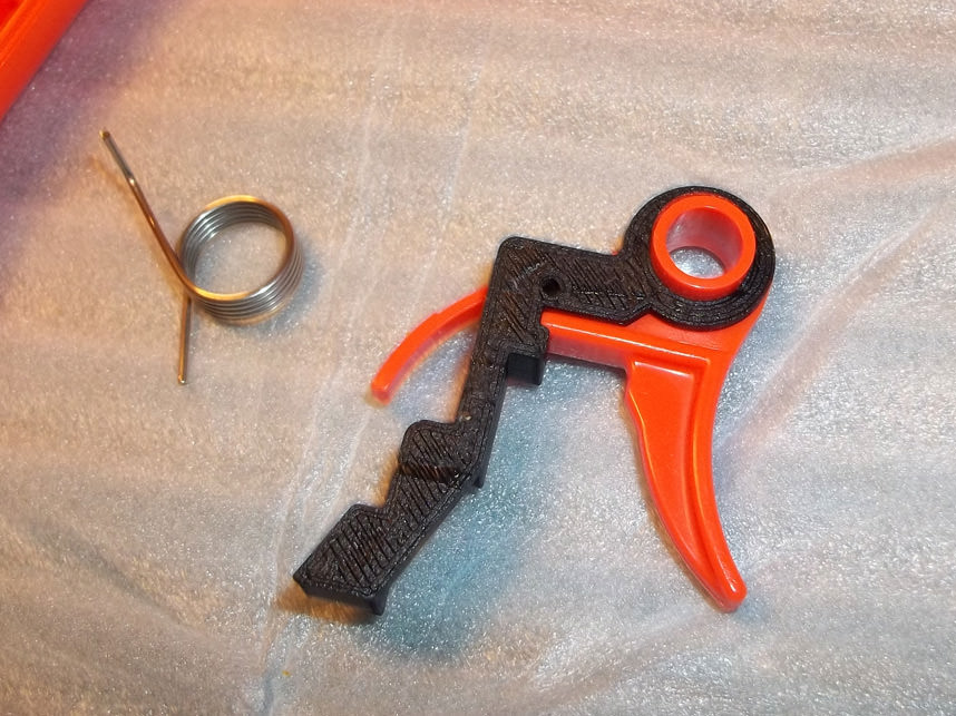
Mated pieces as shown.

9. Spring Insertion
The spring slips into the back of the trigger as shown, be sure that it pokes through the tiny hole and extends past the new plastic or your trigger won't seat properly.
10. Testing Trigger
Place the trigger back into position as shown, be sure to test the action to verify that it will activate the switch.

11. Adjustment
It's time to put the controller cord back in. Bend the tabs of the switch like this to make as much room as possible without touching the neighboring tab.
12. Ferrite
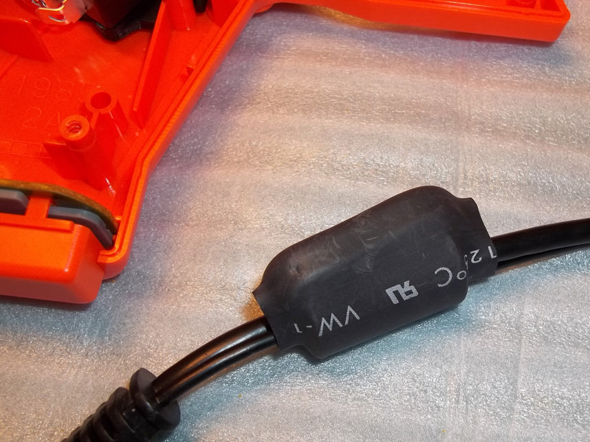
There is a ferrite bead on the controller cord that can prove troublesome when closing everything back up, you'll want to cut away the heatshrink covering it, but be careful not to cut into the insulation of the wires. Don't forget to plug it back into the PCB.

13. Replacement
With the heatshrink removed, you can adjust the loop around the ferrite bead to shift it a little further down if necessary, and also move the cable around until you're able to close the plastic shells together. Alternatively, you could take a hammer and smash the ferrite bead to remove it from the cord, but I personally prefer modifying things in such a way that I can return them 'back to stock' if I ever wanted to.
14. Closure
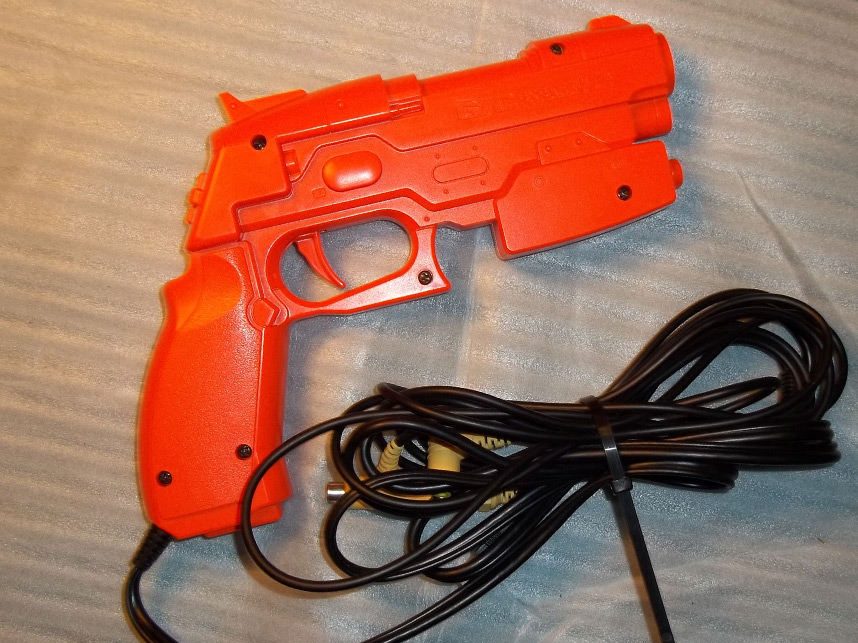
Screw the shell back together and test the trigger action to verify that it's light and springy. If it's not, you'll have to open it back up and rearrange something. Be very cautious that you don't pinch any cords or wires as you close things up. Currently I supply all kits with 50 gram force switches, but you can change that to the switch of your personal preference if you have any.
Made In China Version Addendum Below

Addendum 1
The Made In China Guncon 2 differs from the Made In Japan model in that it has silver screws instead of black. It is compatible with the microswitch kit, but the trigger piece will require a few slight modifications.
Note where the arrow is indicating a chunk of plastic obstructing the trigger from sliding into place.

Addendum 2
Take a utility knife or clippers and trim away this plastic as shown. You won't have to take much.

Addendum 3
Additionally, you will need to file or shave along the edge that hooks around the trigger's 'L' shape. It should be obvious how much material needs to be trimmed away when you attempt test fittings.

Addendum 4
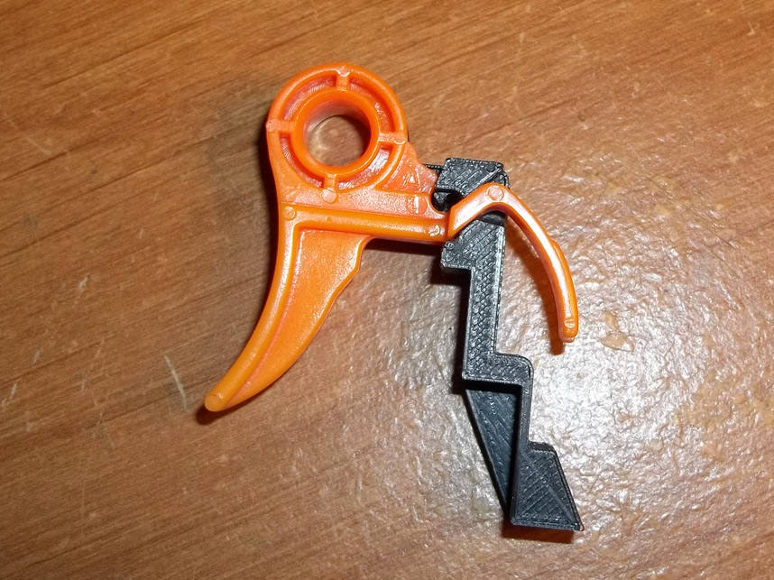
And this is how your piece should look on the Made In China version Guncon 2 trigger.
Addendum 5
Obverse side of the finished piece.