
Nintendo N64 Controller Z-Button Microswitch Kit Guide
1. Introduction
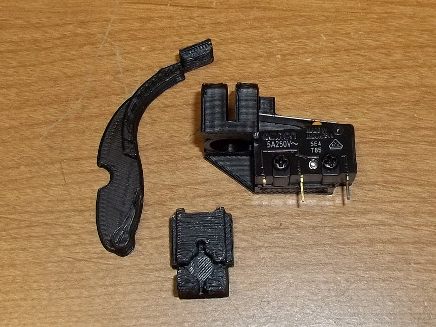
This kit replaces the original conductive membrane for the N64 controller Z-button with a levered microswitch. Actuation force and travel of the Z-button remains the same but benefits from a more tactile feel with a satisfying and positive click.
As with the majority of my kits this is a completely reversible modification and a relatively easy installation too, but you'll still need to use a soldering iron as the guide outlines below.
2. Opening
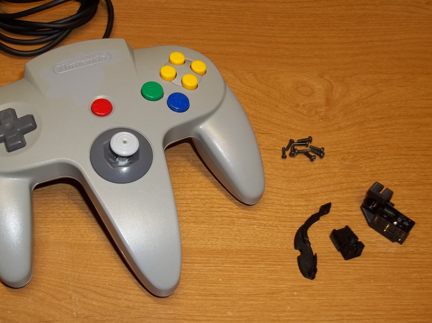
Remove all of the screws from the N64 controller shell. There are three parts to this kit, an actuation arm, z-button anchor and finally the bracket that holds the switch.
3. Disassembly
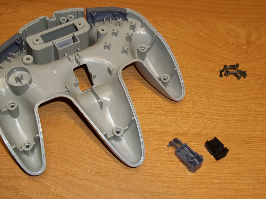
With the controller shell opened up take out the PCB and I recommend uncoupling the gray plastic Z-button cap so you can more easily insert the anchor and arm, but they can be inserted without taking the Z-button cap out if you're careful.
4. Button Cap & Anchor
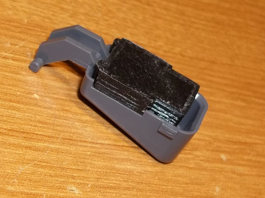
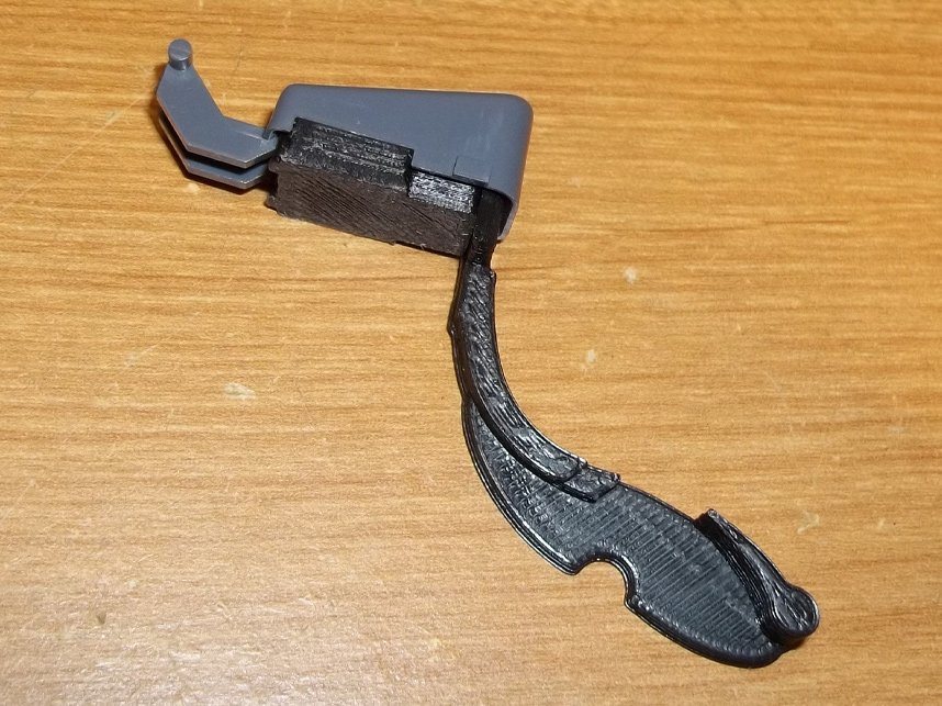
The anchor is keyed to go into the interior of the cap only one way- note the gap at the bottom, this is where the actuation arm slides in.
5. Actuation Arm
The actuation arm is also keyed to only go in one way. In the first picture it's not completely inserted- there is a slight lip that will indicate when it's stuck in all the way (it also won't go any further past this lip.)
6. Actuation Arm Continued
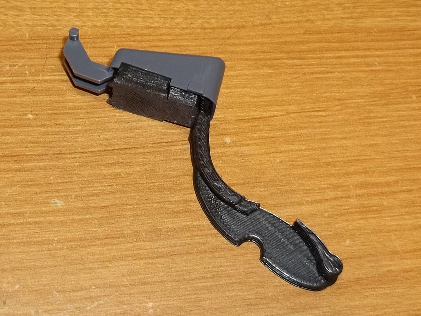
Another view of anchor and actuation arm completely inserted into the Z-button cap.
7. Reinsertion
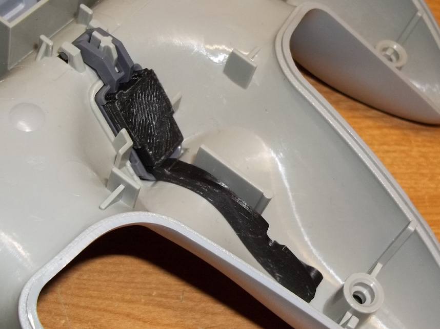
You'll know everything is in place once you clip the Z-button cap back into place, the arm's curve will conform nicely to the interior plastic of the controller shell.
8. Bracket Placement
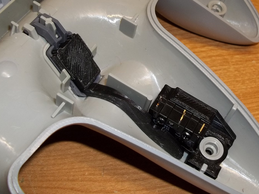
The switch bracket comes next and is inserted like so on the middle prong's screw post. This would be a good point to test the Z-button's action to verify that it works as intended, like a trigger on a lightgun.
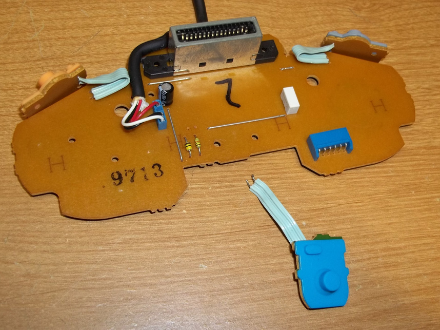
9. Removing Old Contact
You will need to desolder the original Z-button PCB and conductive membrane assembly so there is room for the kit.
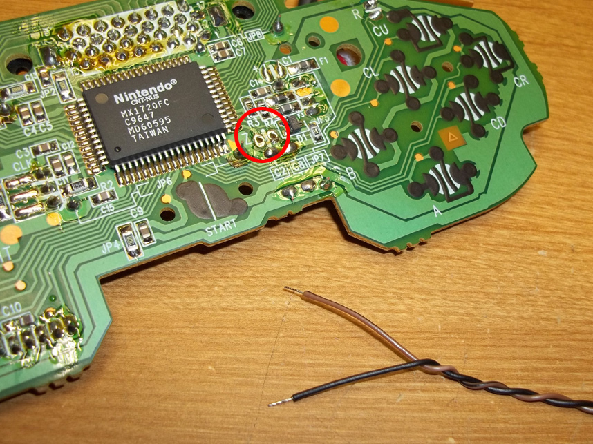
10. New Wiring
Prepare some wire by stripping/tinning it, I like to braid mine so everything's neat but it's not necessary. You'll want to solder these wires to the two points circled in red, but it should also be marked though the PCB's silkscreen that that this is the 'Z' input.
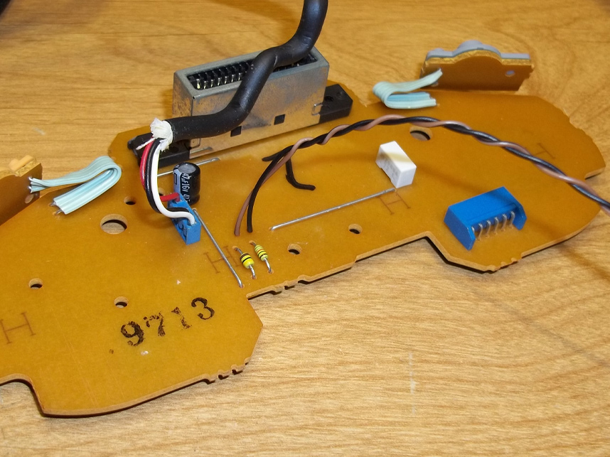
11. Board Connection
The wires should be coming through the back half (brown side) of the PCB.
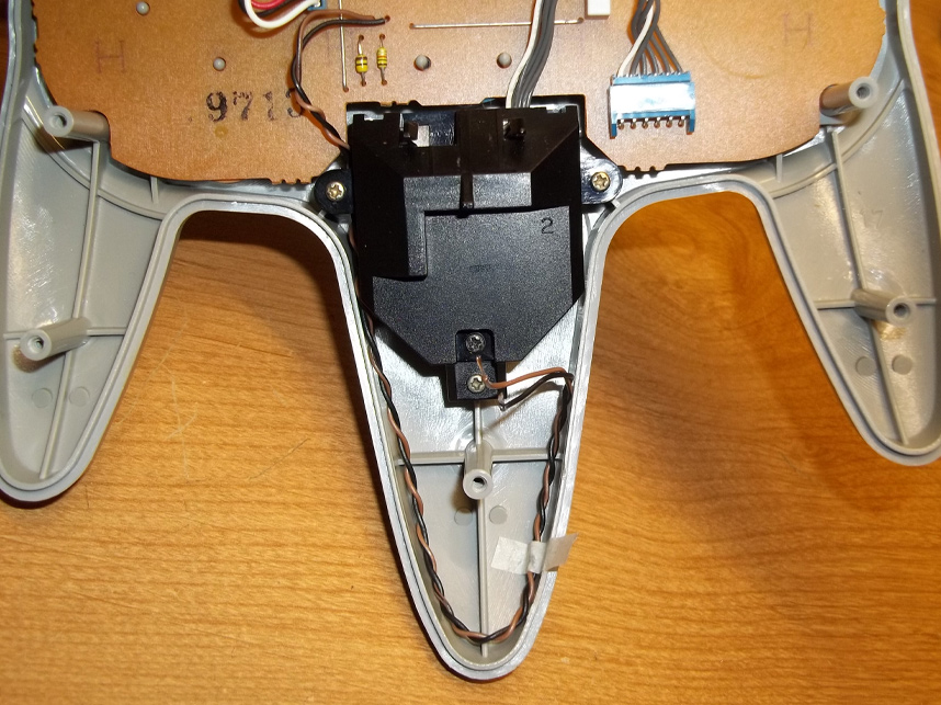
12. Replacement & Routing
I recommend routing the wire like so, but feel free to run it however you see fit. The idea is to keep things tidy so it won't interfere with the motion of the action arm, the levered switch, or pinch in between any screw posts, etc.
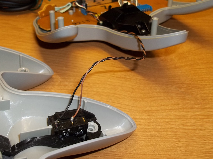
13. Wiring Switch
Finally solder the other end of the wires to the normally open and common posts of the switch. It doesn't matter which goes where, this is a simple open/shut circuit.
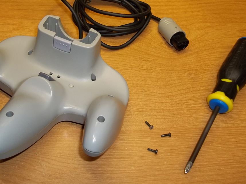
14. Closure
Close everything back up being mindful not to get the wires pinched while the controller shell's coming together and screw it all shut. Give the controller a test run with a game!