
Genesis/SNES Konami Justifier Trigger Kit Guide
1. Introduction
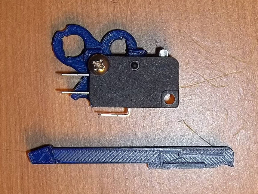
This kit installs a microswitch inside of the Konami Justifier lightgun, for improved response and a hair trigger. Though designed for the Sega Genesis model the mold is likely the same for the SNES version and should fit. Nonetheless, open yours and check just to be sure!
Note that there could be some dimensional variance in the injection molded parts that the 3D printed parts fit into. You may have to perform some filing or use a razor/sharp knife to widen holes if things are too tight. I design these kits to be snug as it's better to have excess material instead of 'not enough.'
2. Opening
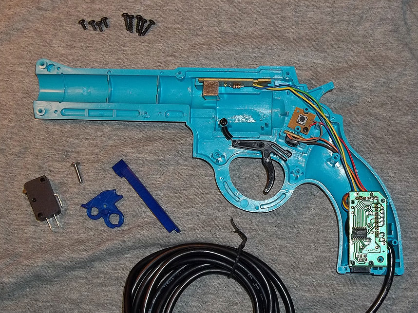
Opening the Justifier is a little trickier than most light gun housings as in addition to screws there are plastic pegs in one half snugly mating with holes in the other. After removing all of the screws you'll probably get best results gently prying open from the barrel and sliding a plastic card along the seam, working it up as you go.

3. Placing Bracket
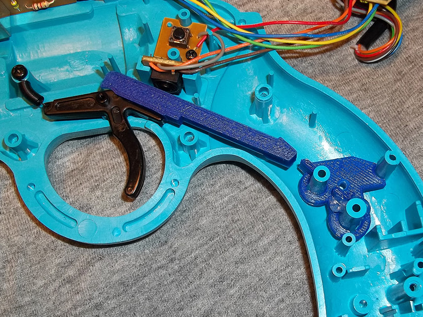
The switch bracket slips into the pegs shown above, and should be wiggle-pressed down as far as you can get it, just be careful you don't press too hard to avoid breaking anything. A dot of hotglue will help keep it from moving out of alignment later.
Basically, this bracket has to be low enough that with the switch in place, the two gun halves can come back together.

4. Trigger Fitment
The second piece mates with the trigger as shown and is designed to be a snug fit. Still you'll want to avoid snapping any plastic so if it's too tight, use a small handfile where necessary. You can use a dot of hotglue afterwards if you've rendered it too loose.
5. Placing Trigger
Place the trigger into place as shown- once the microswitch is in place, it will no longer hit the original trigger button so you won't have to remove it. I have had someone report back that their trigger extension -was- hitting the original button and had to file down plastic, so you may just want to relocate or remove this button board if necessary.
6. Optional Trimming
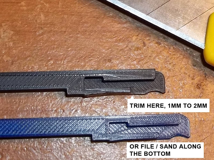
A note if you find the trigger piece is nudging into the switch too closely- you can trim away as shown above, or file/sand along the bottom edge. The idea is to keep the jaws of the trigger from spreading once the extension is added to it.

7. Wiring
You will want to connect wires from the common and normally open tabs of the microswitch to the points shown on the original button board. It shares a ground wire with the start button so it's easier to leave it in if you can get away with it.

8. Installing Switch
Screw the switch into the bracket and route the wires so you'll be able to close the gun up later, watching out that nothing gets pinched. Hotglue dots can help here! Be sure to test the trigger action afterwards.
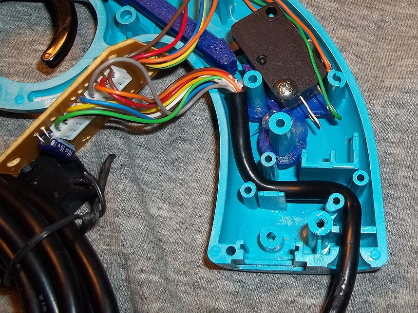
9. Layout
Now the main board's controller cable should be laid into place like this,
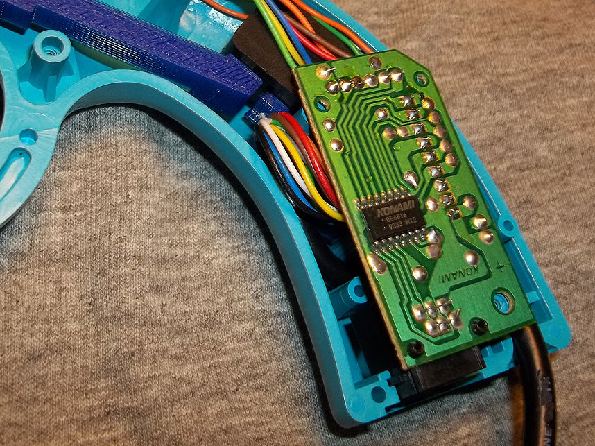
10. Testing & Closure
And then the colored wiring should tuck back and under as shown. This is to prevent it from interfering with the actuation of the trigger piece. Make sure no wiring is getting pinched anywhere, especially underneath the main board. You may have to use something long and flat to keep the wiring from getting caught between the two halves as you close the gun back up.