
Sony PS1 Konami Guitar Freaks Microswitch Kit Guide
1. Introduction
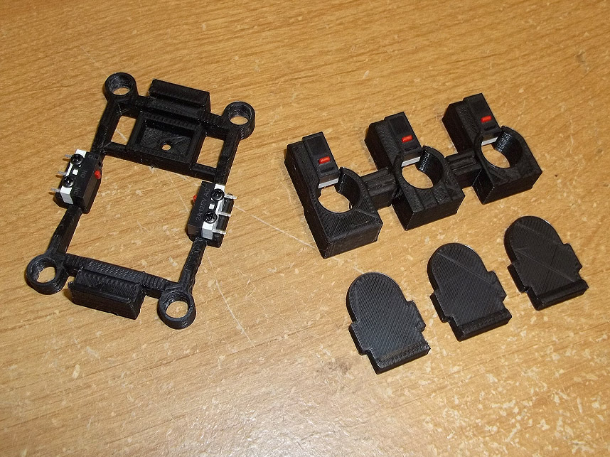
The Konami Guitar Freaks switch kit replaces the conductive rubber membranes of the pick and frets with clicky microswitches which provide tactile feedback that you're hitting the notes you're trying to make. This includes a pick harness, a 3-piece fret harness, and 3 fret button shims. You will need wire in lengths of about 14-15 inches, I recommend 28AWG or 26AWG.
Note that there could be some dimensional variance in the injection molded parts that the 3D printed parts fit into. You may have to perform some filing or use a razor/sharp knife to widen holes if things are too tight. I design these kits to be snug as it's better to have excess material instead of 'not enough.'
2. Opening
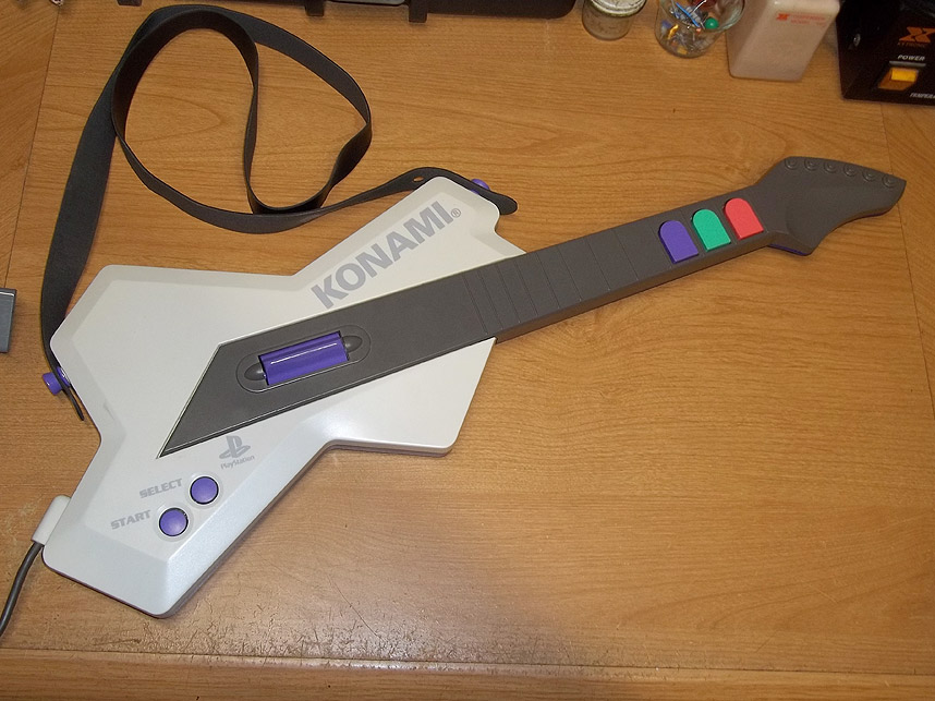
First you'll need to disassemble the guitar controller- remove all the screws in the back and flip it over to access the guts.

3. Disassembly
Then you'll want to unscrew all of the circuit boards inside, pull out the rubber conductive membranes, and the gray plastic piece that sits between the main controller board and the pick rocker. Set all this stuff aside.
4. Controller Board
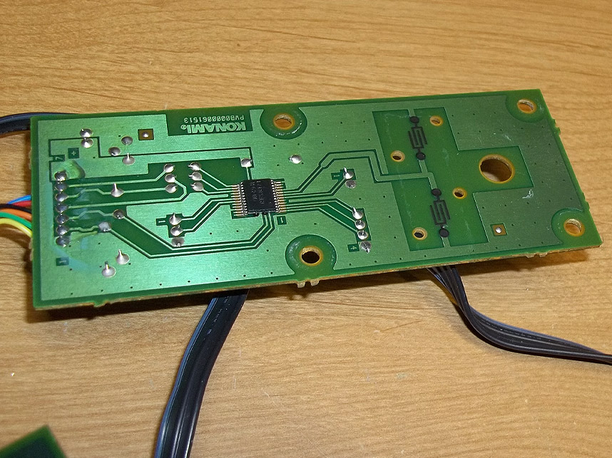
This is the main controller board which you'll be tapping into with new wiring to connect the kit's 3D printed plastic harnesses and their respective switches. Pin 8 of the 24-pin chip is the pick signal, but it's much easier to simply scratch away some phenolic from the large trace extending from it to solder to than the pin of the chip itself. Lower below, four solder points lead to the fret board that was located in the neck of the guitar. Note that ground is marked #4 on this side of the board...

5. Solder Points
And on the obverse side, you can see the ribbon cable with #4 and #1 marked on the PCB. The pinout is:
1: Red
2: Green3: Blue (or Purple)
4: Ground
You'll want to desolder this ribbon cable and completely remove the fret board.
6. Removing Cable
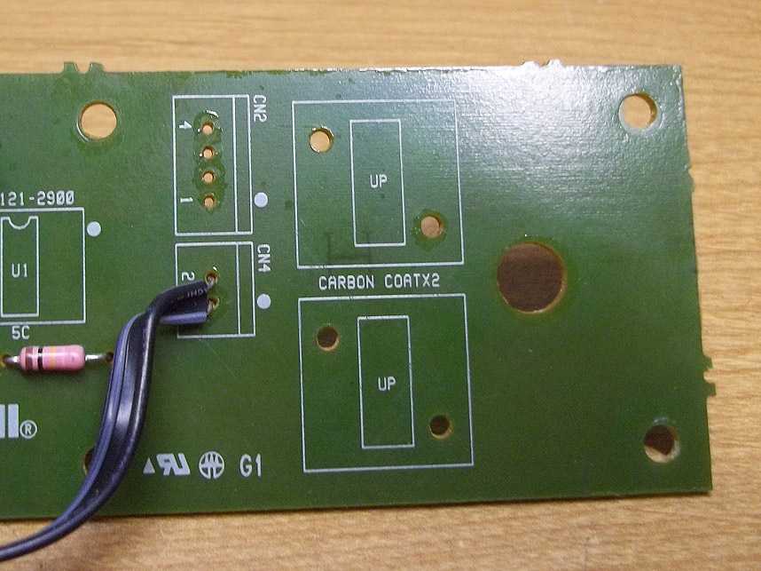
Here is the main controller board with the original cable removed.

7. Making Connections
Solder 4 new wires of 14 to 15 inch lengths to the respective common (C) and normally open (N/O) pins of the switches on the new fret harness included in the kit. I suggest wiring ground to the common pins via daisy chaining them with short wire lengths so you only have to run one single dedicated ground wire through the neck down to the main controller board.
8. Pick Preparation
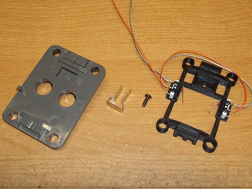
Remember that gray plastic piece that sat over the pick rocker?

9. New Pick Assembly
You'll want to unscrew the metal tines and transplant them to the new pick harness. This metal piece helps return the pick rocker to center position- you may have to bend them closer together a bit with pliers to make them return to center better if they've been stretched out a bit from time/use. You can also now wire in the common and normally open pins of the pick harness switches as shown above, give yourself plenty of length to work with later.

10. Soldering Wire
Solder the normally open pin of the pick harness switches to pin 8 of the 24 pin chip located on the main controller board. As mentioned before you can scrape away some green coating of the trace that leads out from it and solder there. It's easy to identify this trace as it goes to those two carbon contacts that the rubber conductive pads originally used.
11. Placement
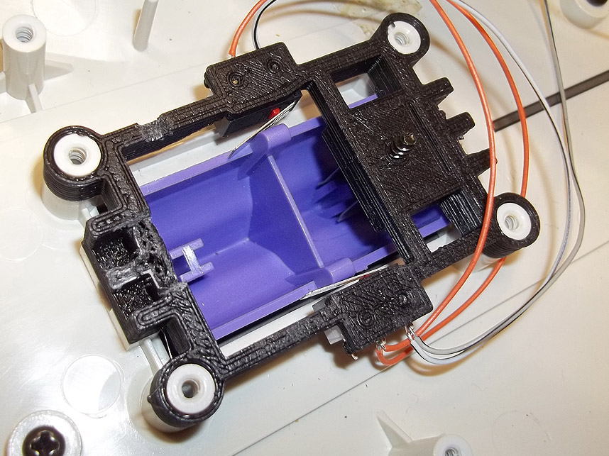
Now slip the pick harness into place as shown, you may have to gently spread the metal tines with a screwdriver so it will go over the purple rocker's center post, while its actuating levers clear the switches going to either side of it. Test the rocker now to verify that both switches can be triggered and reset when the rocker is at rest.

12. Fret Preparation
Pretty simple step here, place the fret button shims into position, they have a ridge at the bottom so the frets now have a rolling/rocking action similar to how a computer mouse button works.

13. Closure
It's time to button things back up. Return the main controller board into place over the pick harness and screw it in, making sure that none of the new wiring gets pinched. I've made cutout gaps in the pick harness frame that should allow wiring to be run underneath it on the side closest to the 24-pin chip so make use of that if you need to.
Also note at the top corner of the picture that the fret switch harness has been placed on the back half of the guitar shell, over three injection molded pegs near the top of the neck. If you encounter trouble with them staying in place as you put the two shell halves back together, you can anchor them with a few dots of hot glue.