
Sega Game Gear Console
Converted from handheld to desktop console, only Game Gears with dead or busted screens were salvaged for this very limited run of customized systems. They use GGTV circuit boards from eTim supporting NTSC RGB, S-Video and Composite output which was a hugh upgrade over the original dismal LCD screen that had come out in the 1990s. This project was completed somewhere around Summer of 2020.

1. First Look
These systems were housed in a sloped desktop project box made of injection molded ABS and given decals evocative of the preceding Sega Master System from which the Game Gear's circuitry is heavily based around.
Each came with a custom gamepad that had the start button wired into a traditionally unused pin of the controller ports, but standard Master System gamepads were also supported.
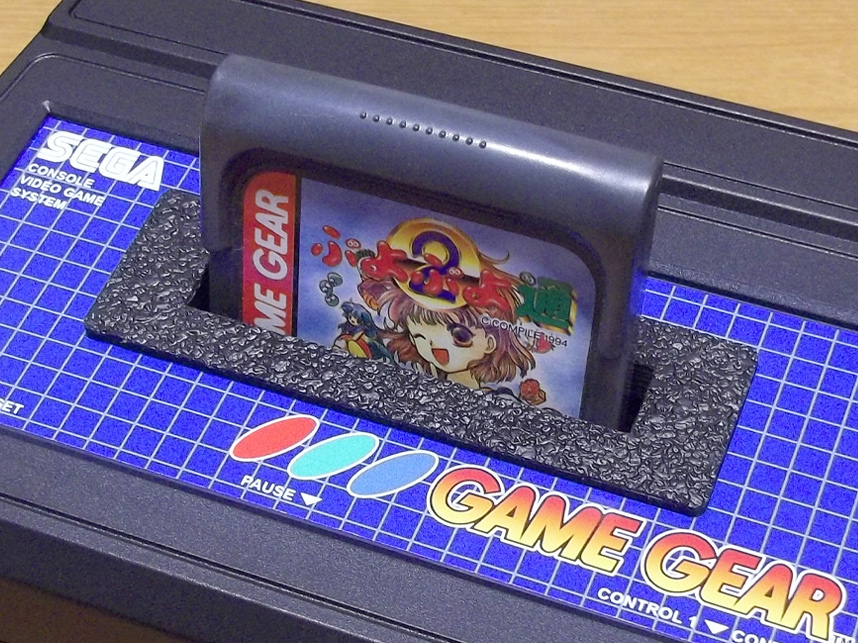
2. Up Close
Cartridges insert through the top just like most game consoles- the connector was realigned on the mainboard and a cart slot with spring tensioned dust flaps was implemented.
Being able to plug a game in this way was considered one of the most important aspects of the entire project, to really sell this item as a system meant to be plugged into a television, no longer a handheld.

3. Link Play
Access to the link port was preserved so a second console could be hooked up for multiplayer. This port was also internally wired to the 2nd controller port to support two players on Master System games, which this console could handle through adapters or more likely, a re-writeable flash cartridge.
On the leftmost television one console is displaying in RGB and on the rightmost display, the Commodore 1702 monitor, a second console is displaying via S-Video.

4. Top Off
A look at the build inside- the enclosure just barely had enough room for everything to fit. 3D printed brackets were used to securely mount it all. Where possible, even the original screws from the Game Gear's previous life as a handheld were reused.
The blue button in the center of the console is an additional option for "start/pause" in the event someone decided to play with a Master System gamepad that didn't have this built in.
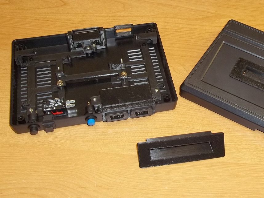
5. Underneath It All
With all of the circuit boards removed, the aforementioned 3D printed brackets are more obvious.
One important design philosophy followed for this project was to make everything internalized as possible. The video/audio/power ports are all inset behind the shell plastic and don't protrude. No screws are visible from the outside either excepting the four which hold the shell together on the bottom.

6. Load Bearing
The transparent green slab represents the mainboard while the opaque green pieces are models of the power and audio boards.
These each had to be mounted with some elevation to either get the cartridge connector at the right height or simply to suspend the power/sound connections behind the plastic wall of the enclosure where holes could be drilled out cleanly.
The GGTV board mounts somewhat in the center to make wiring a simple affair, from the necessary solder points on the mainboard to the video outputs themselves.
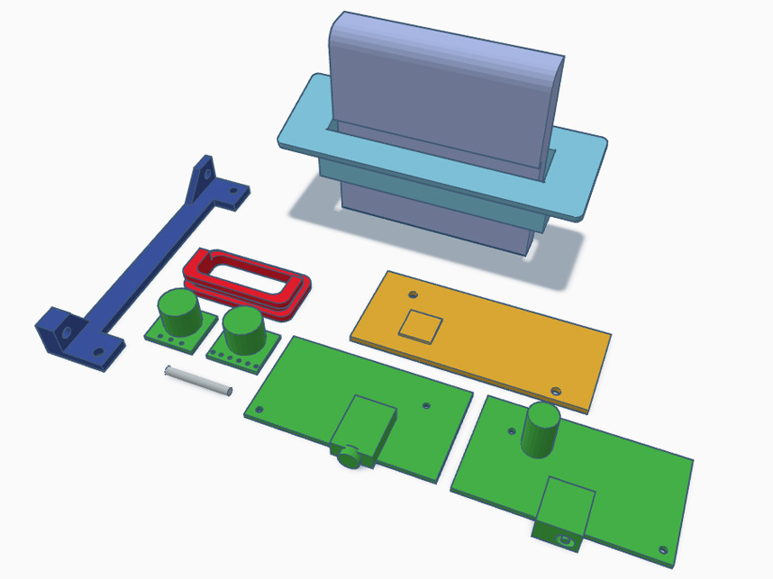
7. So Much Modeling
Cartridge slot bezel, video port PCBs, braces and video/audio/GGTV boards.
Several hours went into designing everything, perhaps one of the most complicated projects undertaken by Magic Trashman Industries to date.
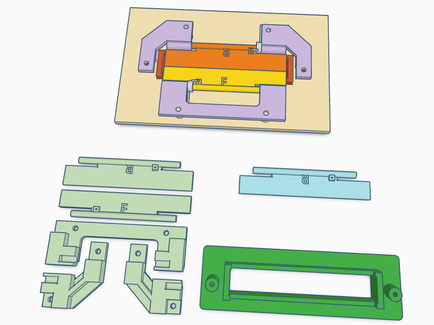
8. Even More Modeling
Detail of the cartridge slot's dust flaps, which yield to an inserted game then snap back into position once the game's been removed. These parts used springs recycled from scrapped VHS tapes.

9. Templates
Several templates were necessary to mark on the enclosure where to drill or cut.
In the case of the cart slot plate just one half sufficed since it could be flipped to pencil in the other side symmetrically.
All other guides were designed to seat onto screw posts already present on the injection molded enclosure along with stencils which hung over the walls of the bottom shell.