
Nintendo NES Advantage Microswitch Kit Guide
1. Introduction
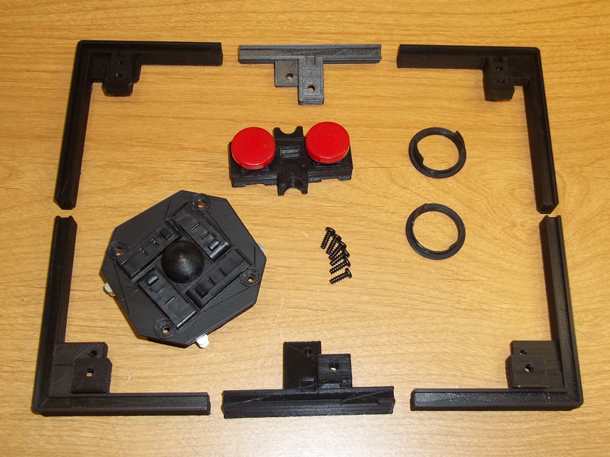
This kit replaces the mushy rubber dome contacts of the NES Advantage joystick and A/B buttons with springy, clicky arcade quality microswitches. No drilling/cutting is necessary and this modification is completely reversible if you ever wish to return the stick to its original conditon.
Included is a harness for the joystick, a six piece base extension to make room for the microswitches in the harness, A/B microswitch module, button bezels and six 3mx8mm screws.
2. Opening
You'll have to open up the NES Advantage to begin, this should be pretty straightforward, remove the rubber feet from the bottom plate to expose the six screws holding it together, pull the gray plastic knobs from the turbo potentiometers and use a 10mm deepwell socket to unscrew the nuts and washer holding the main PCB to the upper plastic housing.
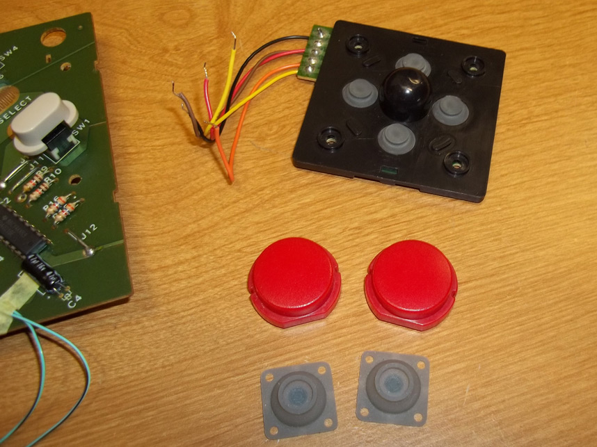
Remove/desolder the following: the original stick harness, the red plastic A/B buttons and their respective conductive rubber membranes, pictured here.
3. Wiring Prep
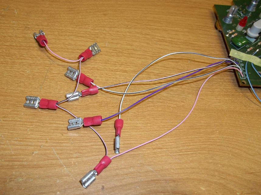
You'll want to prep a wiring harness for the new joystick base, the directions and ground are marked on the main PCB. Quick connects are pictured here but you can solder the wiring directly onto the switches if you want.

4. Connections
Place a non-conductive barrier over the A and B contacts of the main PCB, electrical tape is best, but masking tape or similar will do. Solder wiring to the pictured locations (to replicate function of either button) and tack them down as suggested so that they won't interfere with assembly later.
5. Button Harness
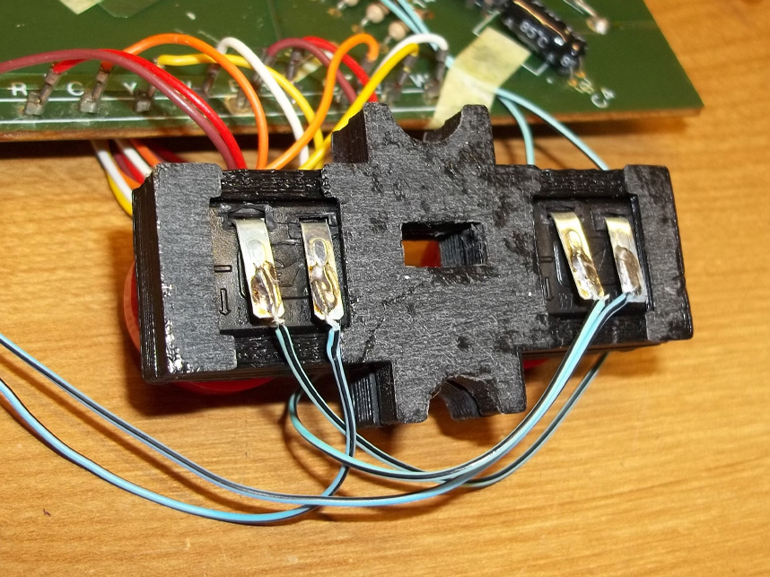
Solder the other end of this wiring to the contacts of the new A/B module, paying attention to their orientation and how it will sit in the top half of the NES Advantage shell. Soldering is recommended instead of quick connects in this case because there isn't much clearance available for the latter.
Looking at the tabs from left to right, connect J2 and J9 for one button, then J1 and J8 for the other button.
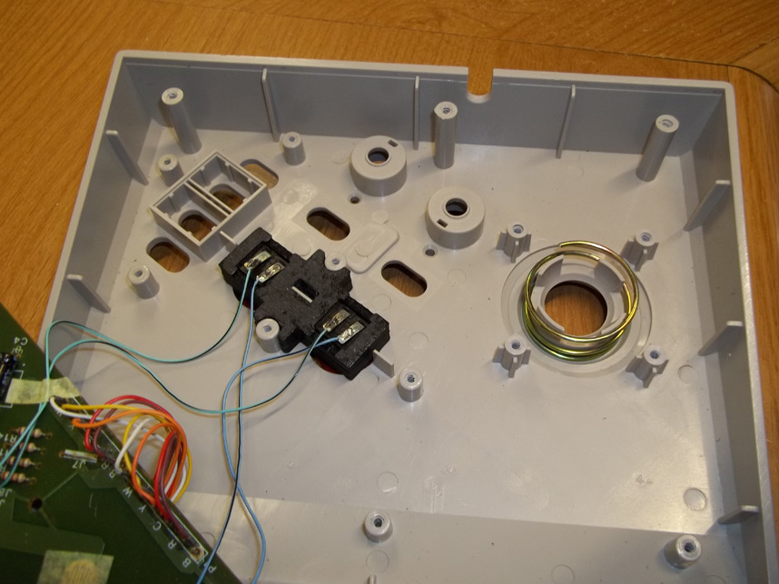
6. Placing Buttons
As you can see this module sits in the top shell only one way, so it's important you don't get the wiring mixed up for A and B or you're going to have to reopen the controller to get at this again.

7. Button Bezels
Since the new buttons sit a little higher than the original setup, a pair of slip-on bezels are included. These can be secured with dots of hotglue from the inside but it's not strictly necessary since they should slide in snugly. Note that they will only go in all the way when the prongs are aligned properly, so be gentle inserting them so you don't snap them.
If you feel that they're too snug or are afraid you're going to break them, you can try lightly sanding the exterior for an easier fitment. Afterwards you can return the main PCB back into place and screw everything in, making sure you don't snag or pinch any wiring.
NOTICE: This piece has been revised as the prongs aren't really necessary and were too fragile anyway. If you have a bezel piece with these wings/prongs you can slice them off if you like, or keep them on. It's no big deal if they break off.
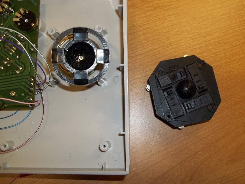
8. Lubrication
This is the replacement harness for the joystick. It's recommended to add some plastic-safe lubricant such as Super Lube to the concave interior of the stick's underside and a little to the dome of the harness too.
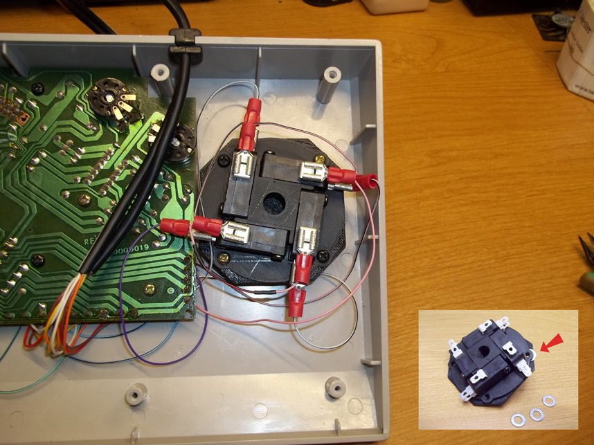
9. Joystick Harness
Mating the joystick harness to the underside of the stick and case top should be fairly straightforward, screw it in, then test the stick to make sure everything moves properly. Afterwards connect your wiring to the switches. Direction lines to the middle tabs (normally open) and ground lines to the shorter tabs (common) at the top.
If for some reason you find a direction sticking, you can slip washers between the switch bracket sandwich like the inset picture depicts to give it just a lil' more clearance. You might need one hole shimmed this way, sometimes all four.

10. Base Risers
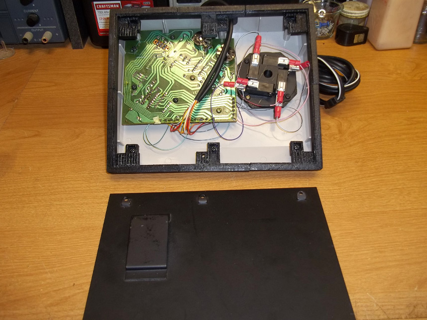
Now you'll want to add the base riser pieces. These are keyed so that you cannot mix them up, they will only go in one way and match with the screw mounts they're supposed to mate with, but to help you better visualize where the six pieces go, these three parts each have 'skinny' mount tabs and cutout slots that match the wall supports of the top shell.
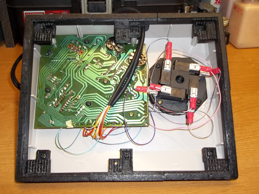
11. Pieces Fitted
This is what you should end up with once the six base pieces are assembled into place properly. Reuse the original machine screws that secured the metal plate for these.
NOTICE: This kit has been revised and sometimes comes with four larger pieces instead of six.
12. Bottom Plate
Now take the metal plate and orient it so that the angled brace at the bottom is situated like so, this is so it does not obstruct the joystick harness nor touch the main PCB underside.

13. Closing Up
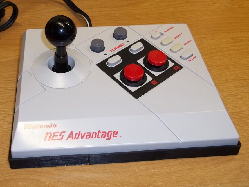
Set the metal base plate into place and screw it in with the new 3mx8mm screws that came with the kit. Now would be a good time to test the joystick to verify functionality.
You can return the self-adhesive rubber feet to the bottom again but it's a good idea to put them in spots that won't obscure the screws in case you ever want to open the controller easily again for future repair/rework.
14. Finished
Modification complete!
If you do not see this kit in stock you can always request more to be made available again through the contact page.